MIL-HDBK-l003/19
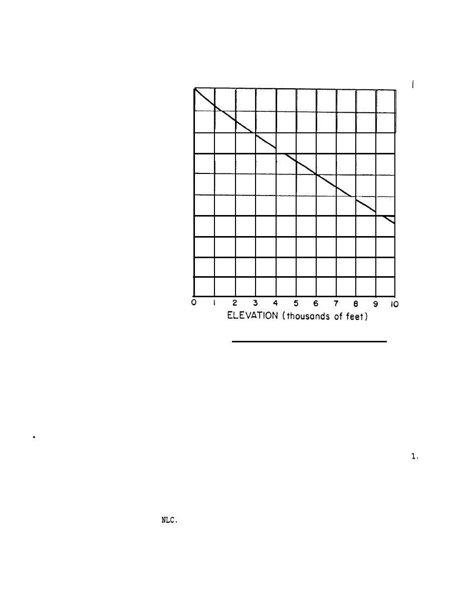
Air density ratio versus elevation.
FIGURE
24.
where Aa is the actual roof area and Rtot is the total Rvalue of the roof
element. If the roof is pitched over a horizontal ceiling with an attic, two
possibilities exist: (1) If the attic is vented RROOF is the total R-value o
the ceiling alone; (2) If the attic is not vented, RROOF is the sum of the
roof contribution, given by equation 5.1, and the ceiling contribution, plus
an allowance for the air gap between the two. If the surfaces bounding the
attic are non-reflective, use an R-value of 0.6 for the air gap and a value o
1.3 if the surfaces are highly reflective.
Worksheet 2 is designed to help the user obtain an estimate of the NLC
after completing the schematic design process outlined on Worksheet
Alternately, the second worksheet may be used as the starting point on
q
subsequent trial designs as the user iterates to improve the performance of
his building.
If the building of interest is a townhouse or other larger structure
containing more than one control zone, Worksheet 2 may still be used to
estimate the
By including the complete structure in the analysis, as
though only one thermal zone were present, one can determine the overall loss
characteristics of the building and estimate the total size of all solar
apertures required to provide a certain level of performance. However, this
overall approach does not help the user to partition the solar aperture among
the various thermal zones.


 Previous Page
