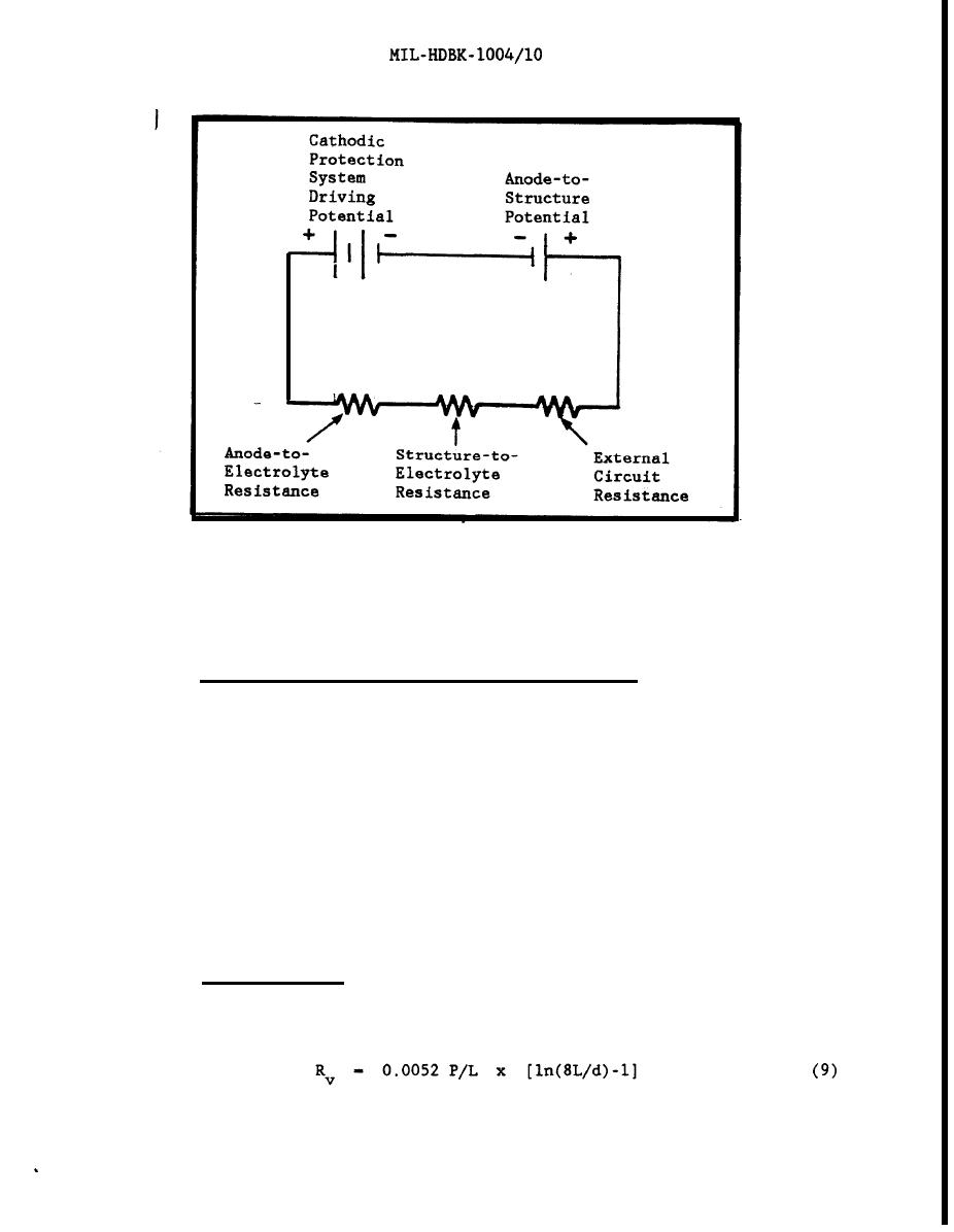
Figure 31
Equavalent Cathodic Protection Circuit
Calculation of Anode-to-Electrolyte Resistance. Anode-to-
6.2.1.2
electrolyte resistance can be computed from data on anode type, size, shape,
and configuration of multiple anode arrays plus the soil resistivity. First,
the type, size, and shape of the anode to be used is chosen. Then, the
resistance of a single anode to be used is calculated. Then the effect of the
use of multiple anodes is determined. However, as the actual environmental
resistivity may not be uniform, or may undergo seasonal variations, the
calculation of anode-to-electrolyte resistivity should only be considered to
be an approximation of the actual resistance to be encountered. This can
result in the actual driving potential required being somewhat different than
the potential calculated using the approximate anode bed resistance. Thus,
after installation, the driving potential must be adjusted to give the
required current output. As the other potentials and resistances in the
cathodic protection circuit vary, the system will also require periodic
adjustments.
Basic Eauations. The formulae developed by H. B. Dwight for a
6.2.1.3
single cylindrical anode can be used to determine the anode-to-electrolyte
resistance. The formula for a vertically oriented anode is:
EQUATION:
54


 Previous Page
