UFC 4-211-01N
25 October 2004
The designer is cautioned that the figure is a simplification of the
existing background information. The information presented is based upon the
assumption that a standard Type I Maintenance Hangar is being produced. It
has been further assumed that the hangar bay space is approximately 30 m
(85 feet) deep and that the design conditions are as found in Norfolk, VA. Figure
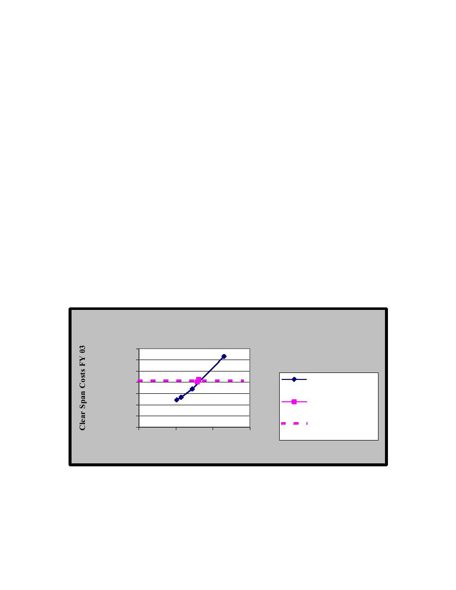
4-1 presents estimated cost based on the pounds per square foot of structural
steel required to construct a facility of approximately 7200 m2 (77000 ft2) total
area. The figures represent an average cost, including both the hangar (OH)
area and the office and shop (O1/O2) areas. It is assumed that the ratio between
OH and O1/O2 areas remains relatively constant in all Type I facilities.
The graphical representation provided by Figure 4.1 shows an
economical comparison of alternative structural framing systems for planning
purposes. The project planning/design team should carefully evaluate the roof
structural framing systems and optimize the design selected considering the
long-term interest of the airfield mission.
NOTE: When generating cost estimates of low bay-type I / high bay-type II single
module versus multiple module and the differences associated with the primary
roof framing system, please contact the NAVFAC Engineering Innovation and
Criteria Office for additional guidance when preparing MCON 1391
documentation.
Figure 4-1 Hangar Clear Span Roof Costs
Hangar Clear-Span Roof Costs
,000,000
,000,000
,000,000
Header-Truss
,000,000
Systems
,000,000
Cantilever Systems
,000,000
,000,000
Cantilever Average
||content||
0
50
100
150
Single Clear Spans, Meters
4-5.8
Roof Systems. Roof systems are typically metal deck on a
combination of open web steel joist and structural steel substructure.
Historically, it has been difficult to maintain the necessary level of quality control
required to weld decks at sidelaps and at supports. The designer is cautioned to
47


 Previous Page
