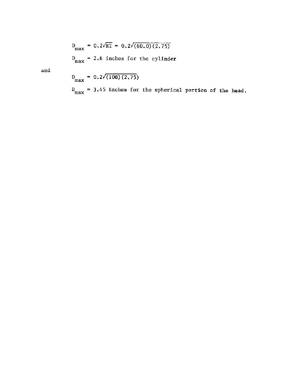
Thus all the major penetrations specified, the entranceway, the viewport
penetrations, and the inlet and outlet nozzles require reinforcement.
(4) Inlet and Outlet Nozzles. The inlet and outlet nozzles are
designed to meet the specifications of paragraphs AD-520, 540.1, 540.2(a) and
Figure AD-540.1(b) as described in the previous example. The geometry of
these nozzles is shown in Figure 2-22. Here the notation [theta] is the
angle that the sectioning plane makes with the plane containing the
longitudinal axis of the cylinder.
(5) Viewport Penetration in Center of End Cap. Here, as before,
it was decided to use the type of viewport as portrayed in Figure 3-6 in
Chapter 3. It will again be assumed that a 10.0 inch diameter penetration is
required. The development of this reinforcement in the center of the
spherical portion of the end cap is exactly as before and the details of this
reinforcement are shown in Figure 2-23.
(6) Entranceway. It is required to have a 40.0 inch inner
diameter entranceway in the center of the other end cap of the cylinder.
The
area to be replaced by some sort of reinforcement is
Ar = dtr = (40.0)(2.72) = 108.8 in.2
with one-half or 54.4 in2 on each side of the centerline of the opening. It
is decided to use, as reinforcement, an inserted, thick-walled cylinder with
inner diameter equal to 40.0 inches. Section VIII, Division 2, gives no
guidance for the design of such a reinforcement.
However, Section VIII,
Division 1, can be helpful in this case. Paragraph UG-40, "Limits of
Reinforcement" states that the limits of reinforcement measured normal to the
vessel wall shall conform to the contour of each surface limited to a
distance from each surface to two and one-half (2-1/2) times the nominal wall
thickness. In this case
Limit = 2.5 x 2.75 = 6.85 inches from each surface.
Choosing a 4.0 inch wall thickness cylinder, the overall height of the
cylinder is
(4.0)(h) = 54.4 + (4.0)(2.75) = 54.4 +11.0
65.4


 Previous Page
