UFC 3-570-06
JANUARY 31 2003
current interruption is required. The data logger records from four to several thousand
readings per second. The measurements taken are not an average over time as with
the digital meters. The location being tested is measured through at least one OFF
cycle and the instant-OFF reading is extracted manually from the data, or extracted via
a computer program that is designed for that purpose. Any positive or negative spiking
that may occur when the current is interrupted or when it goes back on should be
disregarded and is not considered a valid instant-OFF reading. Fast data loggers
record more data resulting in a higher accuracy, but often require more time to
extrapolate the correct reading. Very fast data loggers may require software analysis of
the data to get the instant-OFF readings in a timely manner. Manually verify a
representative sampling of the data to ensure the software is effectively extrapolating
the correct reading. The value recorded using this technique will have from about zero
(0.0003 seconds at 3000 per second) to under of a second (at four per second) of
depolarization, according to the sampling speed of the data logger. It is possible at four
readings per second to record a positive or negative spike as one of the readings
(depending on synchronization timing and the sampling timing of the data logger). In
that case, the next reading would have a full second of depolarization.
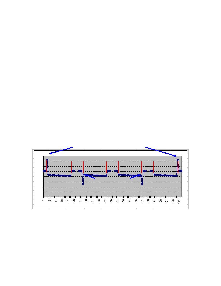
Figure 7-9. Examples of Voltage Spiking on Instant-OFF Readings
Negative Spiking
Negative Voltage
(Can affect ON Readings)
1.025
1.6 .025
1
ON OFF
ON OFF
ON OFF
1.4 .025
1
1.2 1.45
1 .872
0
0.86FF
O7
ON
0.8
0.864
Positive Spiking
0.6
0.861
(Can affect Instant OFF Readings)
0.4
0.858
0.2 .855
0
0 .853
0
Milliseconds
0.851
0.849
7-3.7.3
Using a Waveform Analyzer with a Pulse Generator. The waveform
analyzer is a microprocessor-based hand-held voltmeter that uses a complex computer
algorithm to measure the ON and instant-OFF potentials. To accurately calculate the
OFF potential, a pulse generator must be installed in all rectifiers or DC current sources
that affect the location where the measurement is being made. The pulse generator
interrupts the output of the rectifier on a precise timing cycle. This interruption
generates the precisely timed zero current pulse which is required by the waveform
7-16


 Previous Page
