itself. It is decided to choose a nozzle configuration as shown in Figure
AD-540,1(b), shown here in Figure 2-10. This choice was made for two
reasons: first, such a configuration will not be difficult to fabricate;
second, it is a type of nozzle which can be analyzed for fatigue conditions
due to pressure loadings by the "Stress Index Method" described in Article
4-6. To design such a nozzle, the following procedure should be followed:
o The area on either side of the nozzle centerline (AD-530)
that must be replaced is
A = 0.5 dtr = 0.5(4.0)(2.0) = 4.0 in.2
where
A=
Cross-sectional area of reinforcement
d=
Diameter of finished opening in corroded
condition, in.
tr =
Minimum thickness which meets requirements
AD-702 in the absence of the opening
o Referring to Figure 2-10 here, set tn =
2.5* + inches. The length along the
shell which can be considered for reinforcement
is marked as the "offset" on the figure
or in this case 2.4 inches.
o To determine the height of the nozzle to
beginning of the transition zone, the limit of
reinforcement normal to the vessel wall must
first be established. Paragraph AD-540.2
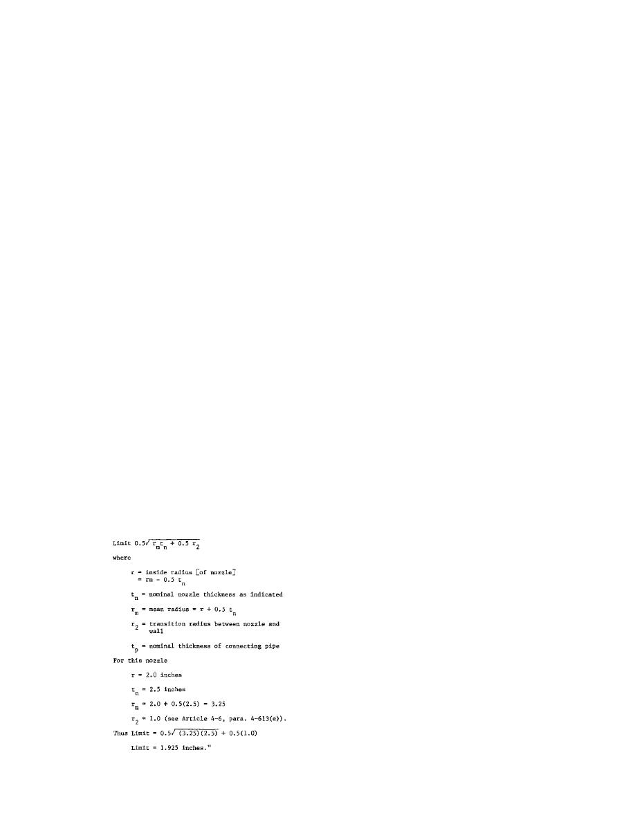
"Boundary Normal to Vessel Wall" states that:
"The limit of reinforcement, measured normal to
the vessel wall shall conform to the contour
of the surface at a distance from each surface
equal to the following limits:
(a)
For Figures AD-540.1(a), (b), and (d):


 Previous Page
