o Thus the effective area of material reinforcement is
Ar = 2.4 x 1.925 = 4.62 in2
which is more than adequate.
o The designer must also check to see that his
design conforms to the boundary limits along
the surface of the shell as prescribed by the
provisions of Paragraph AD-540.2(a), (b), and
(c).
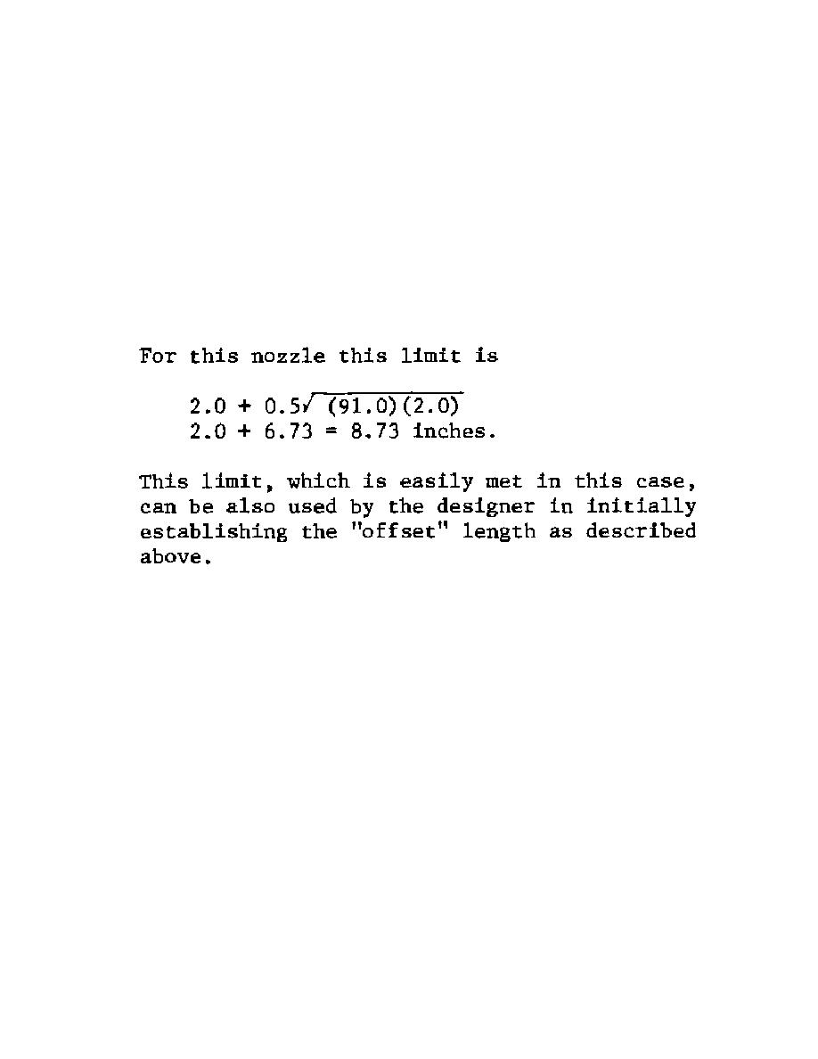
Of particular importance is AD-540.1 (c)
quoted in Paragraph 6.b.(6) above:
For this nozzle this limit is
o The inner corner radius, r1, is established by
Paragraph 4-613(d) as between 10 percent and
100 percent of the shell thickness. In this case,
r1 was set to 0.5 inches which is 25 percent of
the shell thickness.
o The transition radius r3 is established by
Paragraph 4-613(f)(2) as 2(sin [theta])3 times the
offset. For this configuration nozzle,
[theta] = 90.0 degrees and the offset is 2.4 inches.
Thus r3 = 4.8 inches.
o The final 4.0 inch nozzle configuration is
shown here in Figure 2-10. The choice of an
39-47


 Previous Page
