UFC 4-023-03
25 January 2005
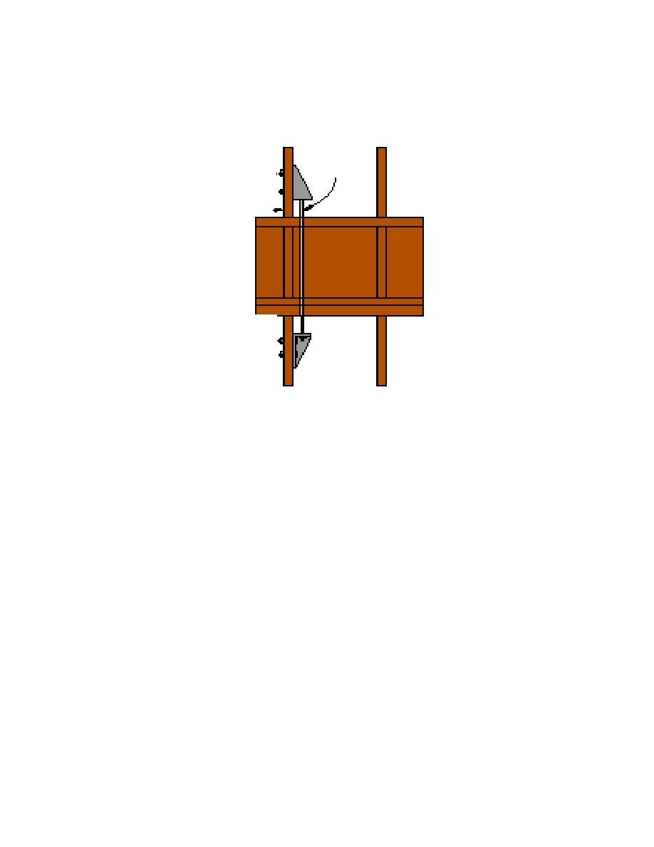
Figure F-6 Holdown Installation for Vertical Ties (Single Shear Shown)
Threaded
rod
Wall stud
Table F-2 and the schematic details show that wood components can easily
carry the required horizontal tie forces, and connections can be designed to transfer
vertical tie requirements. The number of connections and the connection details for
vertical tie forces can be substantial, however, depending on factored loads. Analysis
using the alternate path method to show bridging in lieu of vertical tie capacity may
provide a more economical solution, as discussed next.
F-3
ALTERNATE PATH METHOD FOR WOOD FRAME CONSTRUCTION.
Research on platform wood frame construction has shown potential
mechanisms for bridging over removed members. One mechanism is sheathed walls
acting as deep beams. Consideration should also be given to using a system of rim
beans continuous around the building perimeter at each floor level and at interior load
bearing walls. These rim beams can be designed to support the floor and wall above as
part of the progressive collapse design. Figure F-7 illustrates the use of rim beams.
Figure F-8 illustrates the bridging mechanism enabled through the use of rim beams. In
addition, consideration should be given to building the floor such that the floor is
supported on all sides, even though it is designed to span in one direction. Testing by
TRADA and BRE in the UK demonstrated that the floor has additional strength through
the transverse capacity of the floor that is supported on the walls parallel to the span.
This is illustrated in Figure F-9.
F-8


 Previous Page
