UFC 4-023-03
25 January 2005
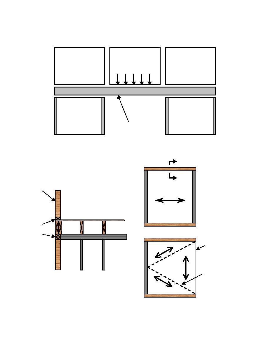
Figure F-8 Illustration of Potential Bridging Mechanism Utilizing Rim Beam
Load from floor
and panel
Header joist/rim beam spans
across gap supported by
adjacent/transverse panels
Figure F-9 Potential Redistribution of Floor Loads
A
A
External
Load
Load
wall panel
bearing
bearing
wall
wall
Floor Span
Nailing
transfers
Floor Plan as designed
forces
Removal
Load
of wall
bearing
wall
beyond
Floor
Section A-A
diaphragm
Floor decking
as a plate
continuous into
wall section
Floor Plan after load
bearing wall removal
F-10


 Previous Page
