161
end of the corridor as their exit path. The functional layout should
allow for the future addition of workbays, if possible.
4.3.9.3 Water runoff from workbay cleaning operations will be
collected in a trench drain located inside the overhead door and
emptied into a grease/oil separator connected to the sanitary sewer.
Designer should verify environmental requirements for drainage with
AR Installation, and local codes and regulations
4.3.9.4 Welding is typically not authorized in an OMS. If authorized,
a code-compliant hood or room must be provided. Comply with
NEC 511 and NFPA 51B; a welding room would require double
doors with a vestibule between if it opens to the workbays. If welding
is not authorized, exterior outlets are sometimes provided for
occasional welding operations, away from any doors. The designer
should verify power requirements.
4.3.9.5 The workbays typically are taller than the other OMS
supporting spaces with a 4.3 m (14 ft) minimum clear height, resulting
in differing roof and wall heights for the two areas. In instances where
it becomes more economical to construct the OMS with one roofline,
use of the area above the ancillary shop spaces for additional storage
and mechanical equipment space is discouraged. The designer must
verify required clear workbay height with Tenants' vehicle sizes.
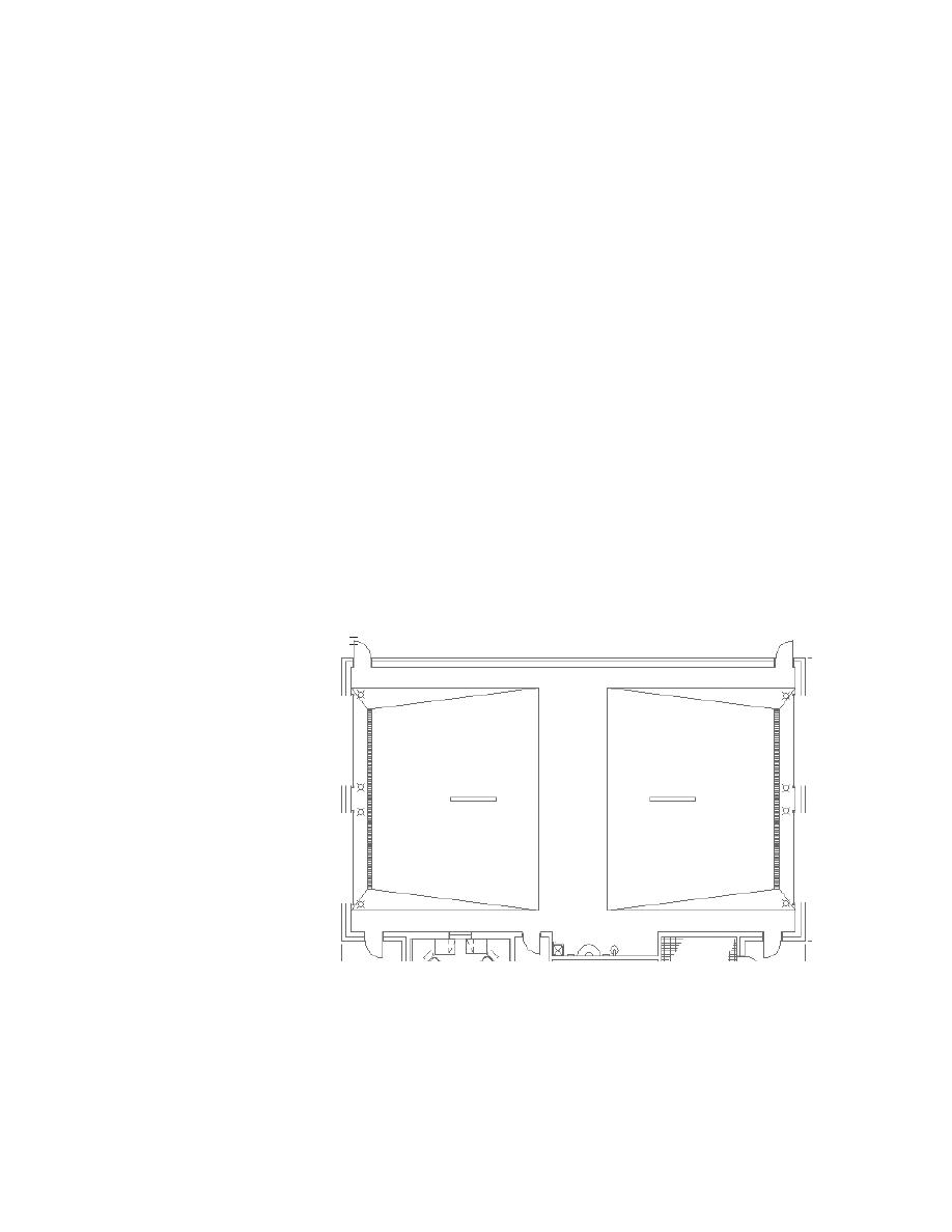
Figure 4-41 Workbays
4.3.9.6 The basic dimensions of the workbays are 6.1 m (20 ft) wide
by 12.2 m (40 ft) long, which includes circulation space along the 6.1
m width. End workbays are authorized an additional 1.2 m (4 ft) of
width on their outboard side to provide circulation space. Trench
drains are located approximately 1500 mm (5 ft) from the exterior
wall, and the floor slopes 75 mm (3 in) to them as shown above.
UFC 4-171-05


 Previous Page
